Difference between revisions of "IOT-DIN-IMX8PLUS: Getting Started"
(→IOT-DIN-IMX8PLUS Overview) |
(→Additional Resources) |
||
| Line 59: | Line 59: | ||
= Additional Resources = | = Additional Resources = | ||
| − | |||
*[[IOT-DIN-IMX8PLUS: Debian Linux: How-To Guide|IOT-DIN-IMX8PLUS Debian Linux How-To Guide]] | *[[IOT-DIN-IMX8PLUS: Debian Linux: How-To Guide|IOT-DIN-IMX8PLUS Debian Linux How-To Guide]] | ||
* [https://www.compulab.com/products/iot-gateways/iot-din-imx8plus-industrial-iot-gateway/#devres IOT-DIN-IMX8PLUS Resources] | * [https://www.compulab.com/products/iot-gateways/iot-din-imx8plus-industrial-iot-gateway/#devres IOT-DIN-IMX8PLUS Resources] | ||
[[Category:IOT-DIN-IMX8PLUS]] | [[Category:IOT-DIN-IMX8PLUS]] | ||
Revision as of 08:20, 11 June 2024
Quick Setup
- Connect a USB cable between host PC and IOT-DIN-IMX8PLUS micro-USB console DBG connector.
- Insert the AC power-supply blade into the power supply unit.
- Insert the power supply plug into the IOT-DIN-IMX8PLUS DC input terminal block.
- On your host PC, start a terminal emulation program (such as Tera Term or PuTTy) with the following serial port settings:
Baud Rate Data Bits Stop Bits Parity Flow Control 115200 8 1 none none
- Plug the power supply unit into an AC outlet. IOT-DIN-IMX8PLUS will turn on and boot into Linux.
- To login into Linux use "compulab" as username and set the password per first login instructions.
IOT-DIN-IMX8PLUS Overview
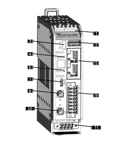
Front panel layout
| Callout | Function |
| 1 | System status indicator. Dual-color blue/amber LED |
| 2 | USB 3.0 connector |
| 3 | User programmable LED A & LED B |
| 4 | User programmable recessed push-button |
| 5 | Ethernet ports, dual RJ45 connector |
| 6 | System reset push-button |
| 7 | Console connector, micro-USB type |
| 8 | Antenna A, SMA * |
| 9 | Industrial I/O terminal block, 16 pin, 16-26 AWG |
| 10 | Antenna B, SMA * |
| 11 | Power input connector |
