Difference between revisions of "Video Input Port Adapter Board"
(→Digital camera sensor connection) |
(→VIP-ADP board setup) |
||
| (2 intermediate revisions by 2 users not shown) | |||
| Line 3: | Line 3: | ||
CompuLab Video Input Port Adapter (VIP-ADP) board is a peripheral board for connecting external video source devices to CompuLab COMs. | CompuLab Video Input Port Adapter (VIP-ADP) board is a peripheral board for connecting external video source devices to CompuLab COMs. | ||
VIP-ADP has a digital camera sensor connection port and two composite video input ports. | VIP-ADP has a digital camera sensor connection port and two composite video input ports. | ||
| − | Analog video is processed by TVP5151 NTSC/PAL/SECAM Video Decoder chip. | + | Analog composite video is processed by TVP5151 NTSC/PAL/SECAM Video Decoder chip. |
VIP-ADP board has several functional modes: | VIP-ADP board has several functional modes: | ||
* Digital video interface | * Digital video interface | ||
| − | * | + | * Analog composite video input inteface |
* Serializer/deserializer interface | * Serializer/deserializer interface | ||
| Line 14: | Line 14: | ||
== VIP-ADP board setup == | == VIP-ADP board setup == | ||
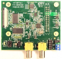
| + | [[Image:Vip_adp_front.jpg|thumb|right|200px|VIP-ADP module front view]] | ||
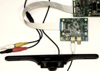
[[Image:Vip_adp_connection.jpg|thumb|right|200px|MT9T031 Camera head board installed on VIP-ADP module]] | [[Image:Vip_adp_connection.jpg|thumb|right|200px|MT9T031 Camera head board installed on VIP-ADP module]] | ||
| − | [[Image: | + | [[Image:vip_adp_n_tvp.jpg|thumb|right|200px|NTSC analog composite camera connected to VIP-ADP module]] |
Following hardware is used as an example of VIP-ADP board connection: | Following hardware is used as an example of VIP-ADP board connection: | ||
| Line 21: | Line 22: | ||
* [http://compulab.co.il/products/sbcs/sbc-t3730/ SB-T35 base board] | * [http://compulab.co.il/products/sbcs/sbc-t3730/ SB-T35 base board] | ||
* Aptina MT9T031 camera sensor installed on MT9T031C12STCH ES demo head board | * Aptina MT9T031 camera sensor installed on MT9T031C12STCH ES demo head board | ||
| + | * NTSC analog composite camera with RCA output and power supply. | ||
| Line 68: | Line 70: | ||
* Connect the camera head-board to connector P7 of VIP-ADP. Make sure to match pins properly. MT9T031 sensor head-board connection example is illustrated in the picture above. | * Connect the camera head-board to connector P7 of VIP-ADP. Make sure to match pins properly. MT9T031 sensor head-board connection example is illustrated in the picture above. | ||
| + | * Connect VIP-ADP P3 to SB-T35 P26 Video Input port with a 40-wire flat cable. | ||
| + | |||
| + | === Analog composite camera connection === | ||
| + | |||
| + | The following VIP-ADP jumper settings are required to setup on-board TVP5151 decoder: | ||
| + | |||
| + | * Remove JP5 jumper. | ||
| + | * Remove J1 jumper. | ||
| + | * Place a jumper on pins marked as "INT" of J2. | ||
| + | |||
| + | Camera connection: | ||
| + | |||
| + | * Remove camera sensor head-board from connector P7. | ||
| + | * Connect analog composite camera RCA connector to VIP-ADP composite input port P1. | ||
* Connect VIP-ADP P3 to SB-T35 P26 Video Input port with a 40-wire flat cable. | * Connect VIP-ADP P3 to SB-T35 P26 Video Input port with a 40-wire flat cable. | ||
Latest revision as of 08:29, 29 June 2012
Contents
Overview
CompuLab Video Input Port Adapter (VIP-ADP) board is a peripheral board for connecting external video source devices to CompuLab COMs. VIP-ADP has a digital camera sensor connection port and two composite video input ports. Analog composite video is processed by TVP5151 NTSC/PAL/SECAM Video Decoder chip.
VIP-ADP board has several functional modes:
- Digital video interface
- Analog composite video input inteface
- Serializer/deserializer interface
The selection between the modes is done by the on-board jumper (JP5).
VIP-ADP board setup
Following hardware is used as an example of VIP-ADP board connection:
- Compulab CM-T3730 module
- SB-T35 base board
- Aptina MT9T031 camera sensor installed on MT9T031C12STCH ES demo head board
- NTSC analog composite camera with RCA output and power supply.
The VIP-ADP board requires the following jumper settings to operate properly:
| JP5 settings | 1-2 | 4-6 |
|---|---|---|
| Serializer/Deserializer | * | |
| TVP5151 Decoder | ||
| Camera sensor | * |
| J1 settings | OSC | EXT |
|---|---|---|
| Select VIP-ADP as a clock source | * | |
| Select external clock source | * |
| J2 settings | INT | EXT |
|---|---|---|
| Select internal power source | * | |
| Select external power source (P6) | * |
Digital camera sensor connection
The following VIP-ADP jumper settings are required to setup the digital camera:
- Place a jumper on pins 4–6 of JP5.
- Place a jumper on pins marked as "OSC" of J1.
- Place a jumper on pins marked as "INT" of J2.
Camera sensor connection:
- Connect the camera head-board to connector P7 of VIP-ADP. Make sure to match pins properly. MT9T031 sensor head-board connection example is illustrated in the picture above.
- Connect VIP-ADP P3 to SB-T35 P26 Video Input port with a 40-wire flat cable.
Analog composite camera connection
The following VIP-ADP jumper settings are required to setup on-board TVP5151 decoder:
- Remove JP5 jumper.
- Remove J1 jumper.
- Place a jumper on pins marked as "INT" of J2.
Camera connection:
- Remove camera sensor head-board from connector P7.
- Connect analog composite camera RCA connector to VIP-ADP composite input port P1.
- Connect VIP-ADP P3 to SB-T35 P26 Video Input port with a 40-wire flat cable.
Known issues
SB-T35
- SB-T35 P26 connector pin 6 (RESET#) is not connected. This pin can be used to reset the camera sensor (not required for Aptina MT9T031 sensor on VIP-ADP board).
- SB-T35 P26 connector shifts 10bit of VIP-ADP camera data signals (PDATA[9:0]) two bits right, making the PDATA[1:0] signals not connected.


