Difference between revisions of "SB-SOM: HOWTO: USB Console"
| Line 2: | Line 2: | ||
[[Image:SB_SOM_bottomview2.jpg|thumb|right|alt=SB-SOM bottom view|<div align="center">SB-SOM bottom view</div>]] | [[Image:SB_SOM_bottomview2.jpg|thumb|right|alt=SB-SOM bottom view|<div align="center">SB-SOM bottom view</div>]] | ||
| − | = Setting up your host PC = | + | == Setting up your host PC == |
| − | # Connect a micro-USB cable (included with the evaluation kit) between the SBC | + | # Connect a micro-USB cable (included with the evaluation kit) between the SBC connector '''P7''' to a free USB port on your host PC. |
# Make sure the CP2104 driver is available with your operating system, otherwise install CP2104 driver onto the host PC from here: https://www.silabs.com/products/mcu/Pages/USBtoUARTBridgeVCPDrivers.aspx | # Make sure the CP2104 driver is available with your operating system, otherwise install CP2104 driver onto the host PC from here: https://www.silabs.com/products/mcu/Pages/USBtoUARTBridgeVCPDrivers.aspx | ||
# Identify the host PC interface and port you will be using for communication with the SBC: | # Identify the host PC interface and port you will be using for communication with the SBC: | ||
| Line 14: | Line 14: | ||
</blockquote> | </blockquote> | ||
| − | = Setting up the Compulab Board = | + | '''More Details:''' ''[[SB-SOM:_Connectors:_P7|connector P7]]''. |
| − | # Make sure jumper | + | |
| − | # Start the system by enabling power through the | + | == Setting up the Compulab Board == |
| − | # Make sure | + | # Make sure jumper '''E3''' is not populated. |
| + | # Start the system by enabling power through the main DC power connector. | ||
| + | # Make sure '''DS3''' LED is ON while '''DS2''' LED is OFF. | ||
# Console messages should appear on your host PC through the terminal emulation program. | # Console messages should appear on your host PC through the terminal emulation program. | ||
| + | |||
| + | '''More Details:''' ''[[SB-SOM:_Connectors:_J6_and_J8|main DC power connector]]''<!--, ''[[SB-SOM:_Jumpers:_E3|E3]]'', [[SB-SOM: LEDS: DS2 and DS3|DS3 LED]], [[SB-SOM: LEDS: DS2 and DS3|DS2 LED]]-->. | ||
[[Category:SB-SOM]] | [[Category:SB-SOM]] | ||
Latest revision as of 06:49, 25 May 2016
Setting up your host PC
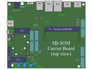
- Connect a micro-USB cable (included with the evaluation kit) between the SBC connector P7 to a free USB port on your host PC.
- Make sure the CP2104 driver is available with your operating system, otherwise install CP2104 driver onto the host PC from here: https://www.silabs.com/products/mcu/Pages/USBtoUARTBridgeVCPDrivers.aspx
- Identify the host PC interface and port you will be using for communication with the SBC:
- For Linux hosts, the serial port in most cases would be called like one of the following (where n is a positive integer): /dev/ttyUSB0, /dev/ttyUSB1 ... /dev/ttyUSBn
- For Windows Hosts, the serial port in most cases would be called like one of the following (where n is a positive integer): COM1, COM2 ... COMn
- Start a terminal emulation program (such as HyperTerminal on Windows or minicom on Linux).
- Within the terminal emulation program, in the serial port configuration section select the port identified in previous step and set the following serial port parameters:
Baud Rate Data Bits Stop Bits Parity Flow Control 115200 8 1 none none
More Details: connector P7.
Setting up the Compulab Board
- Make sure jumper E3 is not populated.
- Start the system by enabling power through the main DC power connector.
- Make sure DS3 LED is ON while DS2 LED is OFF.
- Console messages should appear on your host PC through the terminal emulation program.
More Details: main DC power connector.

