SB-SOM: Connectors: P5
Description
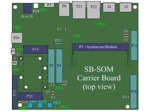
P5 is a 34pin 100mil header. The P5 connector allows easy, jumper-wire oriented, access to various system signals.
The following groups of system-on-module pins can be accessed through P5:
- USBSS - Derived from system-on-module pins 182, 184, 188 & 190.
- HSUSB2 - Derived from system-on-module pins 164 & 166.
- HSUSB3 - Derived from system-on-module pins 158 & 160.
- RTOUCH - Derived from system-on-module pins 66, 68, 70 & 72.
- SATA - Derived from system-on-module pins 21, 23, 27 & 29.
- MISC - Derived from system-on-module pins 11, 13, 152, 161, 163, 179, 187, & 194.
- CAN - Always accessible, this is the physical layer side of the onboard CAN bus transceiver and isolator, allowing direct system connection to a CAN bus.
| Please refer to SB-SOM carrier board schematics and system-on-module hardware reference manual for pin functions, connector pinout and other details on your specific system. |
Connector Data
P5 connector Manufacturer MFG P/N Jih_Vei_Electronics 21N22564-34M10B-01G-6/1.5 –C

