MCM-iMX93: Evaluation Kit: Hardware Guide
Contents
- 1 Overview
- 2 Block Diagram
- 3 Connector Locations
- 4 Interfaces and Functions
- 4.1 DC Power
- 4.2 Serial Console
- 4.3 Serial Download Programming (SDP) port
- 4.4 Display and Touch-Screen
- 4.5 Audio
- 4.6 USB
- 4.7 SD card
- 4.8 mini-PCIe socket
- 4.9 SIM card socket
- 4.10 Ethernet
- 4.11 WiFi and Bluetooth
- 4.12 CAN bus
- 4.13 UART
- 4.14 I2C
- 4.15 SPI
- 4.16 GPIO
- 4.17 ADC
- 4.18 Reset
- 4.19 Boot Sequence Selection
- 4.20 RTC
- 4.21 JTAG
- 4.22 LEDs
- 4.23 Jumpers Summary
Overview
Terms and Definitions
- SoM – System-on-Module.
- SBC – Single Board Computer.
- MCM-iMX93 – System-on-module product based on the NXP i.MX93 SoC. More information here.
- SB-MCMIMX93 – A carrier board, designed for evaluation and development with MCM-iMX93.
- MCM-iMX93 Evaluation kit – A combination of MCM-iMX93 SoM and SB-MCMIMX93 carrier-board accompanied by a set of accessories. More information here.
Additional resources
- All additional materials for MCM-iMX93 and SB-MCMIMX93 are available here.
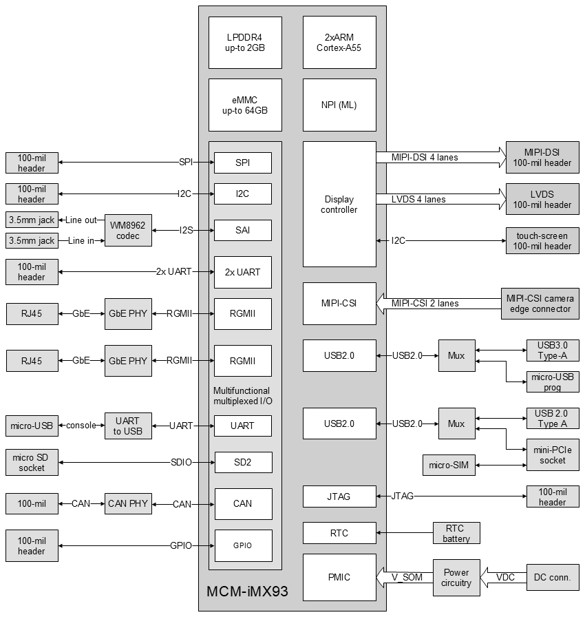
Block Diagram
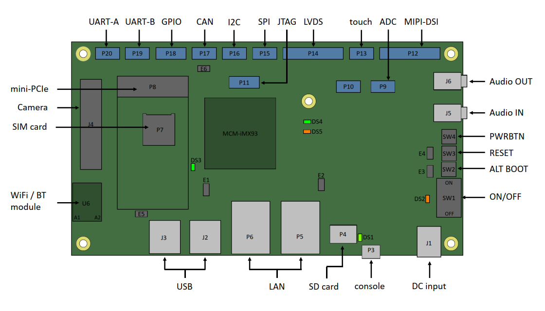
Connector Locations
Interfaces and Functions
DC Power
Main power should be supplied using 12V DC power supply included in the evaluation kit. Adapters for European AC and US AC outlets are included. Connect the power supply to DC input jack J1.
ON/OFF switch SW1 switches main DC power. To turn on the system, switch SW1 to ON position.
Serial Console
To begin using serial console connect your host PC to the micro-USB connector P3 using the USB cable from the evaluation kit.
Serial Download Programming (SDP) port
USB SDP interface is available on micro-USB connector P21 which located on the bottom side of the board under USB connector J3.
The SDP interface can be used for device recovery and firmware programming using the NXP UUU utility.
MCM-iMX93 can be forced into Serial Download Mode by shorting jumper E4.
Display and Touch-Screen
LVDS
LVDS signals are available on header P14.
MIPI-DSI
MIPI-DSI signals are available on header P12.
Touch-Screen
I2C-based touch-screen interface is available on header P13.
Connecting KD070HDTLA020 7" LVDS LCD panel
To connect Startec KD070HDTLA020 7" LCD panel use the EB-HDRLVDS adapter board (supplied with the LCD panel).
Connect the LCD data cable to adapter connector P7. Connect the LCD touch-panel cable to adapter connector P8.
Connect the adapter to LVDS and touch headers P14 and P13.
Audio
SB-MCMIMX93 features on-board Wolfson WM8962 audio codec.
Analog audio line output is routed to audio jack J6.
Analog audio line input is routed to audio jack J5.
USB
SB-MCMIMX93 features two USB2.0 ports that are derived from the i.MX93 USB sub-system:
- Connectors J2 and J3 – USB type-A connectors
SD card
SB-MCMIMX93 supports SD card storage through micro-SD socket P4.
Pressing and holding the ALT-BOOT button SW2 during power-up or hardware reset forces MCM-iMX93 to boot firmware from the SD card.
mini-PCIe socket
SB-MCMIMX93 provides mini-PCI socket P8 that is can be for evaluation of USB-based modules such as 4G cellular modem.
NOTE: P8 socket does NOT provide PCI Express signals.
SIM card socket
uSIM card socket P7 is connected to mini-PCIe socket P8.
An active SIM card should be installed into P7 for operating a cellular modem in mini-PCIe socket P8.
Ethernet
SB-MCMIMX93 provides two Gigabit Ethernet port via RJ45 connectors P5 and P6.
WiFi and Bluetooth
SB-MCMIMX93 features an on-board Azurewave AW-CM276NF wireless module U6.
The module supports 802.11ac WiFi and Bluetooth 5.3 BLE.
To use the wireless functions use antenna cables to connect WiFi antennas (supplied with the eval-kit) to U6 antenna connectors A1 and A2.
CAN bus
CAN bus interface is available via header P17.
CAN bus on-board termination can be enabled by shorting jumper E6.
UART
Two UART interfaces are available on headers P19 and P20.
I2C
I2C interface is available via header P3.
Please refer to MCM-iMX93 reference guide and SB-MCMIMX93 schematics for details.
SPI
SPI interface is available via header P15.
Please refer to MCM-iMX93 reference guide and SB-MCMIMX93 schematics for details.
GPIO
GPIO signals are available via header P18.
Please refer to MCM-iMX93 reference guide and SB-MCMIMX93 schematics for details.
ADC
ADC signals are available via header P9.
Please refer to MCM-iMX93 reference guide and SB-MCMIMX93 schematics for details.
Reset
Pressing the reset button SW3 triggers system hardware reset.
Boot Sequence Selection
Pressing and holding the ALT BOOT button SW2 during power-up or hardware reset forces MCM-iMX93 to boot firmware from an SD card in socket P4.
RTC
RTC is implemented on MCM-iMX93 and receives power from coin-cell battery BH1.
Jumper E5 must be shorted for correct RTC operation.
JTAG
JTAG interface is available via header P11.
Please refer to MCM-iMX93 reference guide and SB-MCMIMX93 schematics for details.
LEDs
- DS1 - Indicates connection of USB host to console port.
- DS2 - Indicates presence of 12V power on the DC input jack.
- DS3 - Indicates V_SOM power rail is enabled.
- DS4, DS5 - user LEDs. Controlled by MCM-iMX93 GPIOs.
Jumpers Summary
- E1 - USB2 multiplexing between mini-PCIe socket P8 and USB connector J2.
- E2 - V_SOM power rail current measurement.
- E3 - force MCM-iMX93 to perform firmware boot from SD card.
- E4 - force MCM-iMX93 to enter serial download mode (SDP).
- E5 - RTC battery power.
- E6 - CAN bus termination control.
Default state:
- Jumper E5 is populated