SB-SOM: Connectors: P23
Description
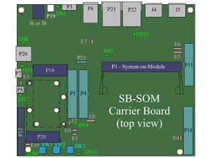
P23 is a 4pin 100mil header designed to allow easy evaluation of CAN bus functionality. P23 is available with all SB-SOM carrier board configurations (board rev1.2 or later).
P23 serves two functions (simultaneously):
- Allows translation of system-on-module CAN interface signals (usually RX and TX signals at TTL levels) into the CAN_H and CAN_L signals ready for connection to a CAN bus node (CAN physical level) as instructed below:
- Connect system-on-module CAN TX (output) signal should to pin P23-1 using a jumper wire.
- Connect system-on-module CAN RX (input) signal should to pin P23-4 using a jumper wire.
- System-on-module CAN interface signals (CAN RX and CAN TX) are in most cases accessible through one of the below SB-SOM connectors:
- Connector P4
- Connector P5
- Connector P11
- Connector P18
- Allows enabling/disabling SB-SOM onboard CAN bus termination resistance (120Ω) as instructed below.
- Populate a jumper cap shorting pins P23-3 and P23-2 to enable CAN bus termination.
- Remove jumper cap from pins P23-3 and P23-2 to disable CAN bus termination.
| Please refer to SB-SOM carrier board schematics and system-on-module hardware reference manual for pin functions, connector pinout and other details on your specific system. |
More Details: Connector P4, Connector P5, Connector P11, Connector P18.
Connector Data
P23 connector Manufacturer MFG P/N Jih_Vei_Electronics 21B1164-04S10-01G-6/3 {ROHS}

