SB-SOM: HOWTO: CAN Connection
Description
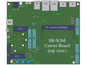
The CAN bus interface available with most SB-SOM is accessible through the P5 100mil header. Use jumper wires to connect your CAN node with SB-SOM CAN bus interface as outlined in the table below.
P5 Pin Signal Name Description 34 CAN_GND Connect to GND terminal your CAN bus interface 32 CAN_L Connect to CAN_L terminal your CAN bus interface 30 CAN_H Connect to CAN_H terminal your CAN bus interface 28 CAN_VCC (5V) If your CAN bus interface requires 5V power, Connect this pin to your CAN bus terminal. Otherwise, Do not use.
120Ω CAN bus termination
CAN bus termination on a node is required with some CAN bus topologies while forbidden with others. SB-SOM board revision 1.2 (or later) features the P23 connector which can be used to enable/disable 120Ω CAN bus termination implemented onboard SB-SOM. Set the bus termination most recommended for your CAN bus topology using P23 connector. Revisions 1.1 and 1.0 of SB-SOM do not provide the CAN bus termination at all.
- Place a jumper cap between pins 2 and 3 of P23 to enable 120Ω CAN bus termination.
- Remove the jumper cap to from pins 2 and 3 of P23 to disable 120Ω CAN bus termination.
More Details: Connector P23, Connector P5.

