SB-SOM: Connectors: P12
Description
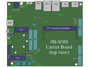
P12 is a SATA connector enabling operation of standard 2.5' or 3.5' SATA drives with the system. Connector P12 is available only in case SATA interface is available at pins 21, 23, 27 and 29 of system-on-module.
The following parameters determine whether SATA at connector P12 is enabled:
- Type of device (mSATA/PCIe/USB) snapped into miniPCIe/mSATA connector P20.
- Jumper E10 setting.
LED DS7 indicates whether the SATA interface is available through connector P12 during system operation.
| Please refer to SB-SOM carrier board schematics and system-on-module hardware reference manual for pin functions, connector pinout and other details on your specific system. |
12V SATA power
By default, SATA drive power supplied through connector P12 includes 3.3V and 5V rails. If your SATA drive requires 12V rail as well, make sure to:
- Populate the FB6 ferrite bead onto SB-SOM (not populated by default since most SATA drives do not require 12V).
- Make sure to supply 12V power source to the system through the main DC power connector (J6 or J8).
More Details: Connector P20, Connector J6, Connector J8.
Connector Data
P12 connector Manufacturer MFG P/N Foxconn LD2522F-S04L6
P12 mating plugs Manufacturer MFG P/N Standard SATA drive

