SB-UCM: HOWTO: CAN Connection
Revision as of 14:54, 4 June 2017 by Alexm (talk | contribs) (New page: thumb|right|alt=SB-UCM top view|<div align="center">SB-UCM top view</div> [[Image:SB_UCM_bottomview.jpg|thumb|right|alt=SB-UCM bottom view|<div align="center">...)
Description
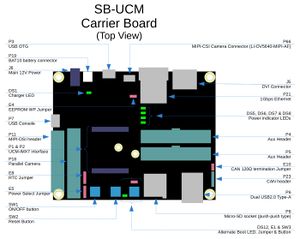
The CAN bus interface available with the system is accessible through P23 header. P23 pinout is outlined below:
P23 Pin Signal Name Description 1 CAN_VCC (5V) If your CAN bus interface requires 5V or provides more than 5V to node, connect this pin to your CAN bus power terminal. 2 CAN_H Connect to CAN_H terminal your CAN bus interface 3 CAN_L Connect to CAN_L terminal your CAN bus interface 4 CAN_GND Connect to GND terminal your CAN bus interface
120Ω CAN bus termination
CAN bus termination on a node is required with some CAN bus topologies while forbidden with others. SB-UCM board features the E10 jumper which can be used to enable/disable 120Ω CAN bus termination implemented onboard SB-UCM. Set the bus termination most recommended for your CAN bus topology using E10 jumper.
- Place a jumper cap onto E10 to enable 120Ω CAN bus termination.
- Remove the jumper cap from E10 to disable 120Ω CAN bus termination.

