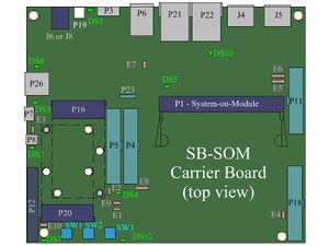
SB-SOM: Connectors: P11
Description
P11 is a 100mil header (output) allowing connection and simple wire-up of an LVDS display panel to the system. P11 is available with all SB-SOM carrier board configurations/revisions. Interface accessible through connector P11 is in most cases derived from either the "LVDS" or the "PDISP" system-on-module pins. Two of the most common implementations are shown below:
- An LVDS interface implemented onboard system-on-module.
- A parallel RGB interface implemented onboard system-on-module is converted into LVDS interface onboard SB-SOM.
Only one of the following SB-SOM display interfaces can be driven with the system-on-module parallel RGB interface at a time. Driving more than one of the below simultaneously is in most cases unsupported.
- A DVI/HDMI display at J5.
- An LVDS display at connector P11 (if implemented through parallel RGB interface with your specific SB-SOM board).
- An LCD display at P10.
| Selection of the parallel RGB interface path (DVI/LVDS/LCD) must be implemented through system-on-module software. |
| Please refer to SB-SOM carrier board schematics and system-on-module hardware reference manual for pin functions, connector pinout and other details on your specific system. |
More Details: connector J5, connector P10.
Connector Data
P11 connector Manufacturer MFG P/N Jih_Vei_Electronics B2264-24S10-01G {ROHS}

