UCM-iMX8M-Mini: Evaluation Kit: Hardware Guide
Contents
Overview
Terms and Definitions
- SoM – System-on-Module.
- SBC – Single Board Computer.
- Evaluation kit – A combination of UCM-iMX8M-Mini SoM and SB-UCMIMX8 carrier-board accompanied by a set of accessories. More information here.
- UCM-iMX8M-Mini – System-on-module product based on the iMX8M Mini SoC. More information here.
- SBC-iMX8M-Mini – A single board computer, which contain UCM-iMX8M-Mini system-on-module and SB-UCMIMX8 carrier-board. More information here.
Reference Carrier Board
- All additional materials for UCM-iMX8M-Mini are available here.
- All additional materials for SBC-iMX8M-Mini are available here.
Additional resources
Getting started with UCM-iMX8M-Mini evaluation kit
Carrier Board
Interfaces and Functions
DC Power
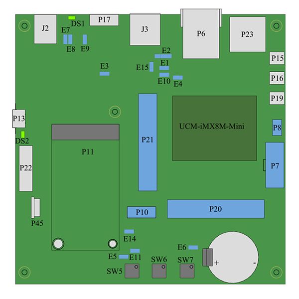
SBC-iMX8M-Mini main power is provided with 12V DC power supply. Adapters for European AC and US AC outlets are included. Connect the PSU to connector J2 before turning on the device.
Serial Console
To start using serial console connect your host PC to the micro-USB connector P13 with the USB cable (included in the evaluation kit).
USB
SBC-iMX8M-Mini features two USB2.0 ports that are derived directly from the iMX8M-Mini USB subsystem.
- Connector P17 – USB2.0 OTG, micro-USB connector;
- Connector J3 – USB2.0 host, type-A connector.
Ethernet
SBC-iMX8M-Mini features one Ethernet port available via RJ45 connector P6.
PCI-Express
Plug your PCI-Express device into the SBC-iMX8M-Mini mini-PCIe connector P11. Full / half size mini-PCIe modules are supported.
Audio
SBC-iMX8M-Mini features analog stereo output (implemented with the WM8731L audio codec) and digital S/PDIF input/output. Both are accessible via the following 3.5mm jacks:
- P3 – Microphone IN;
- P4 – Audio IN;
- P5 – Audio OUT.
Wireless
WiFi/Bluetooth
For WiFi or Bluetooth operation connect the WiFI/BT antenna (included in the evaluation kit) to UCM-iMX8M-Mini connector J1.
Cellular
USB and/or PCI-express interfaced cellular modems (2G/3G/4G etc.) can be plugged into mini-PCIe socket P11. For modem operation:
- Insert the cellular modem into socket P11.
- Insert the SIM card to socket P12 on the bottom side of the board.
- Make sure that jumper E14 is removed (to route the USB interface to the mini-PCIe socket).
Display
The UCM-iMX8M-Mini evaluation kit contains Startec KD050HDFIA020 5" TFT panel with capacitive touch panel.
LCD
To enable the display connect the LCD data cable to connector P22.
Touch panel
To enable the touch-panel connect the touch-panel cable to connector P45.
Camera
The UCM-iMX8M-Mini evaluation kit is compatible with the LI-OV5640 camera module. To start using the camera module connect the module to connector P8.
Multi functional signals access
UART
UART interface is available via header P20.
Please refer to UCM-iMX8M-Mini reference guide and SB-UCM-MX8M schematics for details.
SPI
SPI interface is available via header P21.
Please refer to the UCM-iMX8M-Mini reference guide and SB-UCM-MX8M schematics for details.
I2C
I2C interface is available via header P20.
Please refer to the UCM-iMX8M-Mini reference guide and SB-UCM-MX8M schematics for details.
GPIO
GPIO signals are available via headers P20 and P21.
Please refer to the UCM-iMX8M-Mini reference guide and SB-UCM-MX8M schematics for details.
System
Reset
Pressing the reset button SW6 triggers SBC-iMX8M-Mini cold reset.
Boot Sequence Selection
Pressing and holding the alt-boot button SW7 during power-up or cold reset forces UCM-iMX8M-Mini to boot from SD card.
Power ON / OFF
Pressing the Power On button SW5 shuts down the device.
RTC
For RTC operation make sure that a charged battery is present in socket BH1 and that jumper E6 is populated.
Jumpers Summary
Jumpers:
- E9– SOM power enable.
- E7, E8 – Can be used for the SOM current measurement (only when E9 is not populated).
- E6 – Must be populated for RTC operation.
- E11 – When populated EEPROM is write protected.
- E14 – Controls USB multiplexing. When E14 is populated USB interface is routed to USB connector J3. When E14 is not populated USB interface is routed to mini-PCIe connector P11.
- E4 – When populated debug console routing is forced to micro-USB connector P13. When not populated debug console routing is controlled by auto-detection of USB cable.
Default state:
- Jumpers E6, E9, and E14 are populated;
- Jumpers E1, E4, E7, E8, E10, E12 and E15 are removed.