CL-SOM-iMX7: Evaluation Kit: Hardware Guide
Contents
Overview
Terms and Definitions
Term Definition Evaluation kit A combination of CL-SOM-iMX7 & SB-SOM boards accompanied by a set of accessories detailed here CL-SOM-iMX7 A system-on-module product described here SB-SOM A generic carrier board designed to support several ARM evaluation kits from Compulab. SB-SOM-iMX7 SB-SOM board assembly compatible with CL-SOM-iMX7 system-on-module. SoM system-on-module Reference Carrier Board
The evaluation kit is shipped with a special assembly of the SB-SOM carrier board - SB-SOM-iMX7.
The design materials for SB-SOM (including schematics, PCB layout and Bill of Materials) are available for download from here
Additional resources
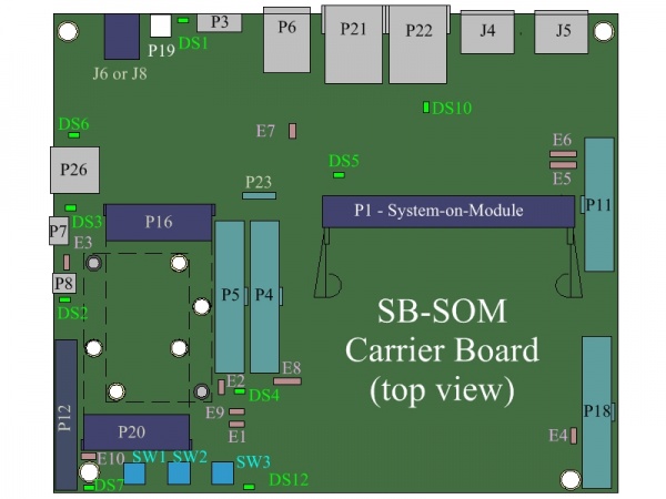
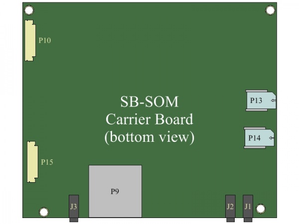
Carrier Board
| The drawing represents a generic SB-SOM board. Some connectors might not be populated in CL-SOM-iMX7 evaluation kit. |
Interfaces and Functions
Main Power
Evaluation kit main power can be provided from either a Li-Poly battery, or a DC power source.
Option 1 - DC only
Connector J6 is the main DC power source of thе evaluation kit. The DC power supply unit included with the evaluation kit provides 12V DC power to the system through J6.
Option 2 - Li-Poly Battery
Battery powered operation of the evaluation kit is supported through the main battery connector P19. The evaluation kit is shipped with an accessory battery adapter allowing P19 connection to custom batteries. Please refer to battery specification for details on supported batteries.
Main Battery Charging
This evaluation kit supports main battery charging when both power sources (Battery + DC) are available. The DS1 LED indicates battery charging is in progress. Detailed status of the battery and charging process is available to software through I2C access to the SB-SOM-iMX7 on-board battery charger (U25 in SB-SOM schematics) and charging supervisor (U24 in SB-SOM schematics).
More Details: Connector J6, Connector P19, Battery Specification.
Serial Console
Serial console is available through one of the following interfaces:
- Serial over USB using micro-USB2.0 Type-B P7 connector. Continue to USB console guide for USB interface setup instructions.
- Serial over RS-232 using the P8 connector with custom RS-232 cable (included with the evaluation kit). Continue to RS-232 console guide for RS-232 interface setup instructions.
More Details: Connector P7, Connector P8, USB console guide, RS-232 console guide.
USB
Both CL-SOM-iMX7 USB ports are accessible with this evaluation kit:
- CL-SOM-iMX7 Native USB Port 1 is available through the OTG connector P3 (only USB2.0 part of the connector is utilized).
- USB Host connection: The micro-USB to USB type-A adapter included with evaluation kit (available for purchase here) allows usage of connector P3 as a standard USB2.0 host port.
- USB Gadget connection: A standard micro-USB cable (included with evaluation kit) enables connection of the evaluation kit as a USB gadget to the USB port of your host computer.
- CL-SOM-iMX7 Native USB Port 2 is available through one of the following connectors, depending on the state of jumper E7.
- E7 not populated: Only Dual stacked USB2.0 P6 connector and P16 mini-PCI-express connector are enabled.
- E7 populated: Only P26 USB2.0 connector is enabled.
- CL-SOM-iMX7 onboard USB hub ports are accessible through the P5 100mil header. Using the CONUSB adapter included with the evaluation kit (available for purchase here), allows connection of standard USB2.0 devices to these ports. P5 pins used for each port are shown in table below
Pin Name HUB port 1 HUB port 2 HUB port 3 Power 5V P5-27 P5-19 N/A Negative Data P5-29 P5-21 P5-1 Positive Data P5-31 P5-23 P5-3 GND P5-33 P5-25 N/A
More Details: Connector P3, Connector P6, Connector P16, Connector P26, Connector P5.
CAN
Two steps are required in order to utilize the CAN bus interface available with the evaluation kit.
- Use jumper wires to connect 100mil header pins where CAN bus functionality (either CAN1 or CAN2 interface) is available (multiplexed), to the P23 CAN header, as shown below:
- For CAN1 interface:
- Use a jumper wire to connect pin P4-2 to P23-1 onboard the evaluation kit.
- Use a jumper wire to connect pin P4-4 to P23-4 onboard the evaluation kit.
- For CAN2 interface:
- Use a jumper wire to connect pin P4-32 to P23-1 onboard the evaluation kit.
- Use a jumper wire to connect pin P4-34 to P23-4 onboard the evaluation kit.
- For CAN1 interface:
- CAN bus nodes can be connected to evaluation kit header P5 as described in CAN node connection guide.
More Details: Connector P4, Connector P23, Connector P5, CAN node connection guide.
Ethernet
The kit features two 1Gbps copper Ethernet ports.
Primary Ethernet
The primary Ethernet port is available through RJ45 connector P21.
Secondary Ethernet
The secondary Ethernet port is available through RJ45 connector P22.
More Details: Connector P21, Connector P22.
PCI-Express
Plug your PCI-Express device into the evaluation kit mini-PCIe connector P16. Full/Half size mini-PCIe boards are supported.
More Details: Connector P16.
Wireless
WiFi/Bluetooth
Connect both antennas (included with evaluation kit) to CL-SOM-iMX7 connectors J1 and J2 for WiFi and/or Bluetooth operation.
Cellular
USB and/or PCI-express interfaced cellular modems (2G/3G/4G etc.) can be plugged into connector P16 (mini-PCI-Express) as explained below:
- Remove jumper E7 to enable USB interface on P16. DS6 LED indicates USB interface availability at P16.
- Plug your modem into P16 mini PCI-Express connector.
- Insert your micro-SIM card into the P13 micro-SIM slot (only relevant if your cellular modem requires a sim card access while not featuring an onboard SIM slot).
More Details: Connector P16, Connector P13.
Display
Evaluation kit supports display interfaces listed below (not simultaneously). Selection of active display interface is set by software.
LCD
LCD panel (included with evaluation kit) is the display enabled by default with CL-SOM-iMX7 linux demo image. Connect the LCD panel the evaluation kit through the FPC connector P10.
DVI
The DVI display interface is accessible through the HDMI connector J5.
LVDS
The CL-SOM-iMX7 LVDS display interface is accessible through evaluation kit header P11. This header enables simple connection (with jumper wires) to any LVDS panel. Please refer to SB-SOM schematics for detailed information on P11.
More Details: Connector P10, Connector J5, Connector P11.
System
Reset
Pressing the reset button (SW2) triggers evaluation kit cold reset.
Boot Sequence Selection
Evaluation kit supports normal and alternate boot sequences. Detailed description of the sequences is available in the CL-SOM-iMX7 reference guide.
- Pressing and holding the ALT.BOOT button (SW3) during power-up or cold reset forces alternative boot sequence.
- Populating the E1 jumper, constantly forces alternative boot sequence.
- Indication of selected boot sequence is shown with the DS12 LED.
Power ON / Cycle
- A short press of the PWRDn button (SW1) while system is operational, generates an OFF request to be serviced by software.
- A long (>5Sec) press of the PWRDn button (SW1) while system is operational, unconditionally shuts down the system (same as simply removing power source).
- A short press of the PWRDn button (SW1) while system is off, triggers the system start-up sequence.
RTC
The evaluation kit RTC (implemented onboard CL-SOM-iMX7) is powered by a coin cell battery. RTC power can be disconnected by:
- Removing the coin cell battery.
- Removing jumper E8.
To quickly discharge the RTC power, momentarily short pins 1 and 2 of jumper E8.
Multi functional signals access
Camera
Part of the CL-SOM-iMX7 camera interface signals are accessible through the evaluation kit P18 header.
Please refer to CL-SOM-iMX7 reference guide and SB-SOM schematics for details.
UART
CL-SOM-iMX7 UART interfaces are partially accessible through headers P4, P5 and P18.
Please refer to CL-SOM-iMX7 reference guide and SB-SOM schematics for details.
SPI
CL-SOM-iMX7 SPI interface signals are partially accessible through headers P4, P5 and P18.
Please refer to CL-SOM-iMX7 reference guide and SB-SOM schematics for details.
I2C
CL-SOM-iMX7 I2C interface signals are partially accessible through headers P4, P5 and P18.
Please refer to CL-SOM-iMX7 reference guide and SB-SOM schematics for details.
GPIO
Some of the CL-SOM-iMX7 GPIO signals are accessible through headers P4, P5 and P18.
Please refer to CL-SOM-iMX7 reference guide and SB-SOM schematics for details.
More Details: Connector P4, Connector P5, Connector P18.
Jumpers Summary
- E1 - Boot Sequence/Production.
- E2 - CL-SOM-iMX7 onboard board specific data EEPROM write-protection.
- E3 - Serial console interface auto detection.
- E4 - SB-SOM board specific data EEPROM write-protection
- E5 - LVDS display connector P11 power source selection.
- E6 - LVDS display connector P11 power source selection.
- E7 - Control of USB interface accessibility through either P26 USB2.0 connector or P6 and P16.
- E8 - RTC coin cell connection
More Details: Connector P11, Connector P6, Connector P16, Connector P26, USB console guide, RS-232 console guide.

